BiSS Interface
Applications
Driver controllers
Smart sensors
Safe actuators
Linear Encoder
Rotary Encoder
Motorfeedback
Description
Features & Options
Serial Synchronous Data Communication
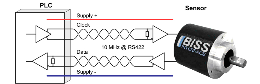
2 unidirectional lines, Clock and Data
Cyclic at high speed (up to 10 MHz with RS422 and 100 MHz with LVDS)
Line delay compensation for high speed data transfer
Request processing times for data generation at slaves
Safety capable: CRC, Errors, Warnings
Bus capability for multiple slaves and devices in a chain
Unidirectional
BiSS C (unidirectional) protocol: Unidirectional use of BiSS C
Bidirectional
BiSS B protocol: Mode choice at each cycle start
BiSS C protocol: Continuous mode
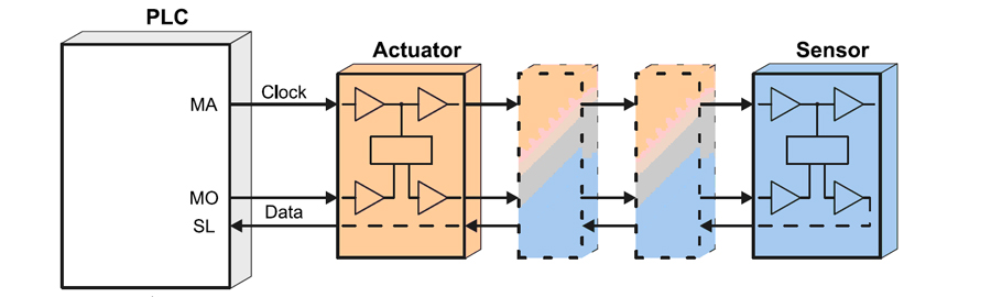
Actuators
Operate actuators via two additional lines
The Technology
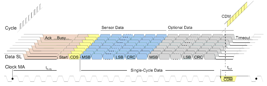
BiSS operates synchronously, serially and cyclically via two unidirectional lines. As the main feature BiSS in addition communicates bidirectionally, both in B and C (continuous) mode.
BiSS is hardware compatible to the standard SSI (Serial Synchronous Interface) and can moreover, even in the unidirectional implementation learn transmission times, thus clocking considerably
faster depending on the line drivers used (up to 10 MHz with RS422 and 100 MHz with LVDS). BiSS can request processing times in all models and is suitable for safety applications thanks to its CRC, error messaging and warning features. BiSS can also be used in sensor buses and can operate actuators via two additional lines.
faster depending on the line drivers used (up to 10 MHz with RS422 and 100 MHz with LVDS). BiSS can request processing times in all models and is suitable for safety applications thanks to its CRC, error messaging and warning features. BiSS can also be used in sensor buses and can operate actuators via two additional lines.
Feature Explanation
The BiSS interface is the ideal interface for sensor and actuator networks, in motion control systems (especially with real-time critical motor feedback) and in machine networking.
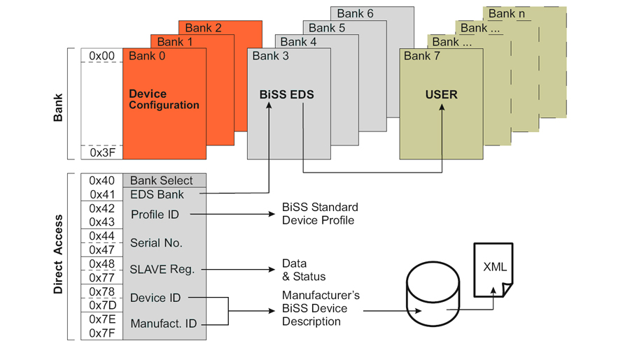
Because of the split bidirectional lines, you can access component registers with BiSS, without affecting the main communication. This register communication is useable for parameterisation and verification,
additional measures, monitoring and diagnosis; also for electronic identification and OEM data access. The memory mapping for device identification, serial number, EDS and OEM data range (electronic ID plate) is defined.
additional measures, monitoring and diagnosis; also for electronic identification and OEM data access. The memory mapping for device identification, serial number, EDS and OEM data range (electronic ID plate) is defined.
All transferred requests and register data, as well as each single cycle channel data, are CRC secured when transmitted, and with an individualised start value, an identification in safety relevant systems is possible.
As well as point to point, bus structures are implementable with the BiSS interface. An unlimited count of devices is supported. With a common clock all activities are triggered simultaneously.
Further information can be obtained from https://www.biss-interface.com/
Additional information
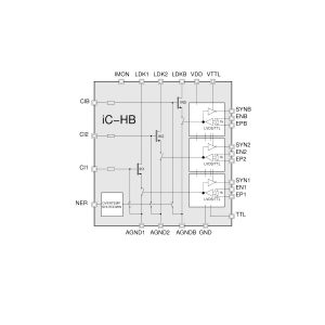
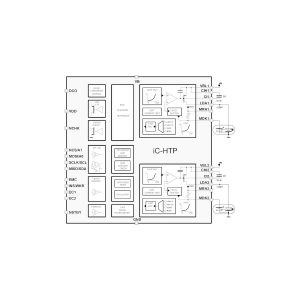
| Type | I/O Circuits – BiSS |
|---|